FLOW OVER TOPOGRAPHY IN RAPIDLY ROTATING FLUIDS
DEMONSTRATE THE CLASSIC TAYLOR-PROUDMAN THEOREM, WHERE FLOW IN A RAPIDLY ROTATING FLUID IS CONSTRAINED TO MOVE AROUND, RATHER THAN OVER, BOTTOM TOPOGRAPHY.
This experiment uses a moderate sized cylinder equipped with thymol blue dye wires to illustrate flow over vs. around topography in a rotating fluid. The cell is sketched below.
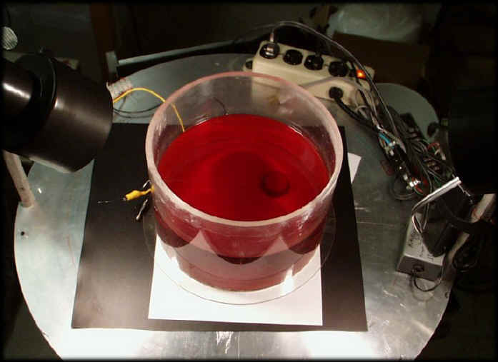
The cell is placed on the Rotating Table Facility. It should be on axis, sitting on a white sheet. Adjust lighting so that sheet is illuminated. Avoid reflections off the water surface into the camera.
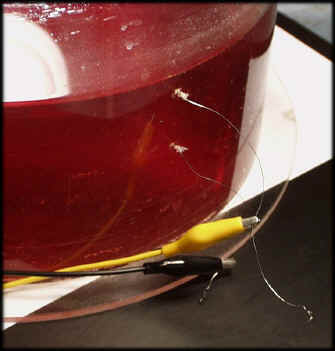
Connect the thymol dye wires to the slip ring AC/DC auxiliary terminals. The terminals on the table should then be connected to the DC supply on the gray-box power supply. Use the banana cable with the pulsing switch on it.
Hook up the container as described above.
Fill to above the top wire height with the orange thymol-water solution.
Turn on camera, lighting, etc.
Focus and adjust camera and lighting prior to rotating.
Set into rotation at a reasonable period (4 seconds or so).
Pulse the dye wires to put in a dark line of dye across a diameter. Flipping the polarity of the dye wire banana cable alternates which wire goes dark
Illustrate small Rossby number motion by changing the rotation rate slightly to allow the fluid to pass over the topography. Choose up or down depending on what is needed so that the solid body rotation will carry the dye towards the bump.
Illustrate high Rossby number motion by making large change in rotation rate, or spinning up from rest.
When finished replace the fluid using a funnel.
Rossby number Ro = change in rotation rate / 2* base rotation rate. If Ro is small Taylor-Proudman theorem says fluid should not cross over the bump, but deviates around it. If Ro is large (infinite for spin up from rest), then fluid can go directly over the bump.
QT MOVIES OF FLOW OVER VS. FLOW AROUND TOPOGRAPHY:
These were made by waiting until solid body rotation is attained, then initiating a dye line by pulsing the dye wires. Just after dye forms along a wire, the rotation rate is changed so that fluid moves in circular solid rotation towards the obstacle. Cases 1,2 have dye formed at the top wire, furthest above the topography. Case 3 has dye injection at about mid-depth in the fluid. Dye may move a bit because of mis-alignment of the table and cell (creating sloshing), or because of evaporation or heating driven convection. These effects may be noticeable but are usually small compared with motion driven by changes in rotation.