ADIABATIC EXPANSION AND GAS LAW PHYSICS (PAUL BUNYAN'S BICYCLE PUMP)
GOAL: To demonstrate changes in P, V, T in a large piston with real time computer-driven graphical display.
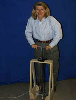
This large transparent air piston may be operated by a student. Expansion or compression is monitored by sensors at the base of the piston and at the top. A small thermal-mass thermocouple wire and a pressure sensor are located below the safety stop, and a travel-distance guage is at the top. These are connected to a computer interface that displays
P(t), T(t) and (optionally) h(t).
This may be used as a qualitative demonstration, or compared with adiabatic theory to generate discussion on the general experiment and on possible non-adiabatic effects. These include conduction from the walls, the small thermal mass of the air sample (compare with the mass of the thermocouple), and small leakage around the piston rings.
The image below illustrates the sensors.
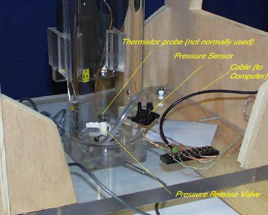
The pressure release valve is used to position the piston. Under normal demonstration conditions it should be closed.
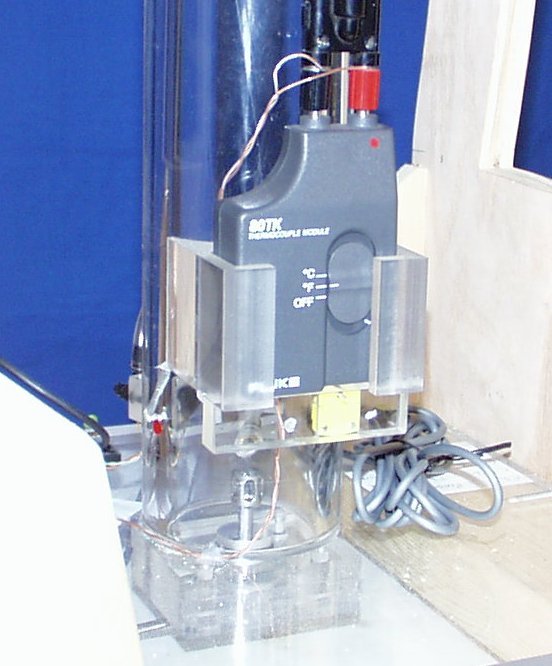
Opposite the probes is a thermocouple module. This should be turned on during the demonstration and off afterwards.
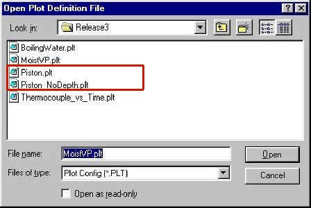
The interface computer contains various plot files in its configuration screen. During configuration choose either of the two files shown (Click and open - see instructions under Computer Interface).
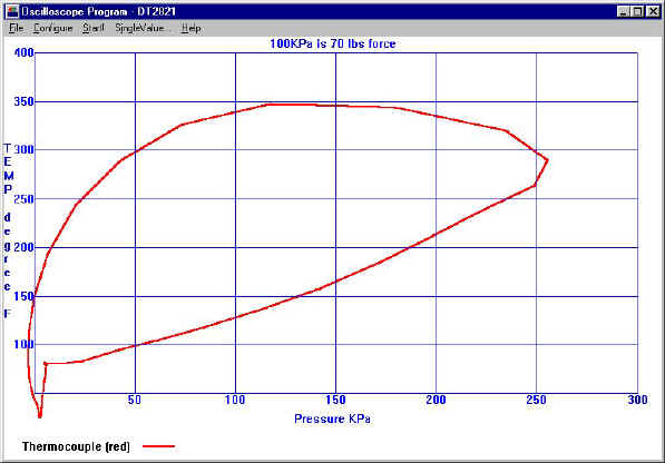
Typical output from the interface computer (above)
Typical result from adiabatic theory (below)
What are possible causes of differences between theory and experiment?
©2000. John Hart, University of Colorado